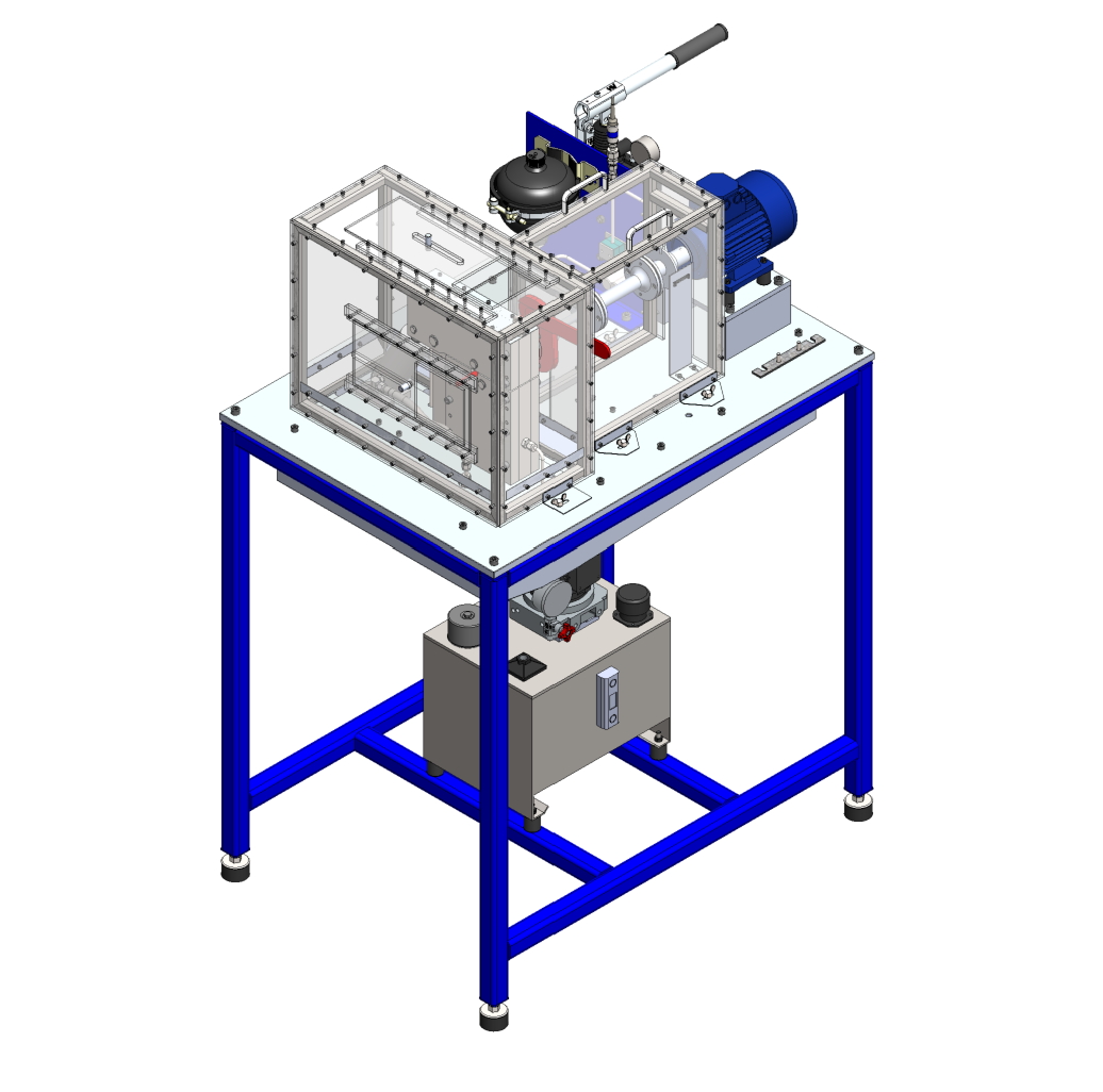
Rod Hardened Surface Rig Test Machine

DTU final project

A DTU bachelor/diploma final project focused on the conceptual development of a specialized test rig for evaluating coated rod surfaces under controlled Hertzian contact pressure, combining tribology, hydraulic loading, shaft verification, and production-oriented drawing work.
Rod Hardened Surface Rig Test Machine
← Back

Overview

This entry presents a concept-stage test rig developed for fatigue testing of chrome-coated rods. The project remained at design stage and was not physically built, but it was developed into a coherent machine concept supported by calculations, assemblies, and detailed technical drawings.

Why this project

The project is relevant because it shows the transition from theory to machine concept. It combines contact-pressure logic, mechanical force transmission, hydraulic actuation, and structural verification in a compact rig architecture designed around a specific testing objective.

Design Principle

The rig was designed around a rotating coated test rod loaded by three support rollers arranged in a triangular configuration. The upper roller applies the main force through a rocker arm and hydraulic cylinder, while the lower two rollers react against that load and create three comparable Hertzian contact zones.

Project Scope

The concept was developed to target rod diameters around Ø10–12.2 mm, Hertzian contact pressure from 1.5 to 2.0 GPa, operating speed around 3000 rpm, oil cooling around the contact zone, axial misalignment compensation in the drive line, safety shielding around rotating parts, and a budget target of 80,000 DKK.

Key Engineering Result

One of the most useful outcomes was the translation from target Hertzian pressure to real hydraulic demand. The calculations showed that the required pressure range could be reached with a compact hydraulic setup rather than a much heavier industrial system.

Technical Output

The strongest technical outputs were the triangular functional unit, the Hertzian contact-pressure calculations, the rocker-arm force path, the shaft verification under worst-case loading, and the transition from concept to assembly and part drawings.

Project Limits

This was a concept-stage academic project, not a finished industrial machine. The rig was not physically built, not every fabricated part was fully strength-dimensioned, shaft verification received priority because it belonged to the main force path, and several detailed verification tasks remained outside the main project scope.

Drawing Package

A public technical drawing package can be linked separately from this entry. The strongest sheets are the main assembly, the functional unit, the rocker arm, the rocker-arm shaft, and the cylinder assembly.

Open technical drawing package (PDF)

Concept-stage DTU test rig for coated rod fatigue evaluation.
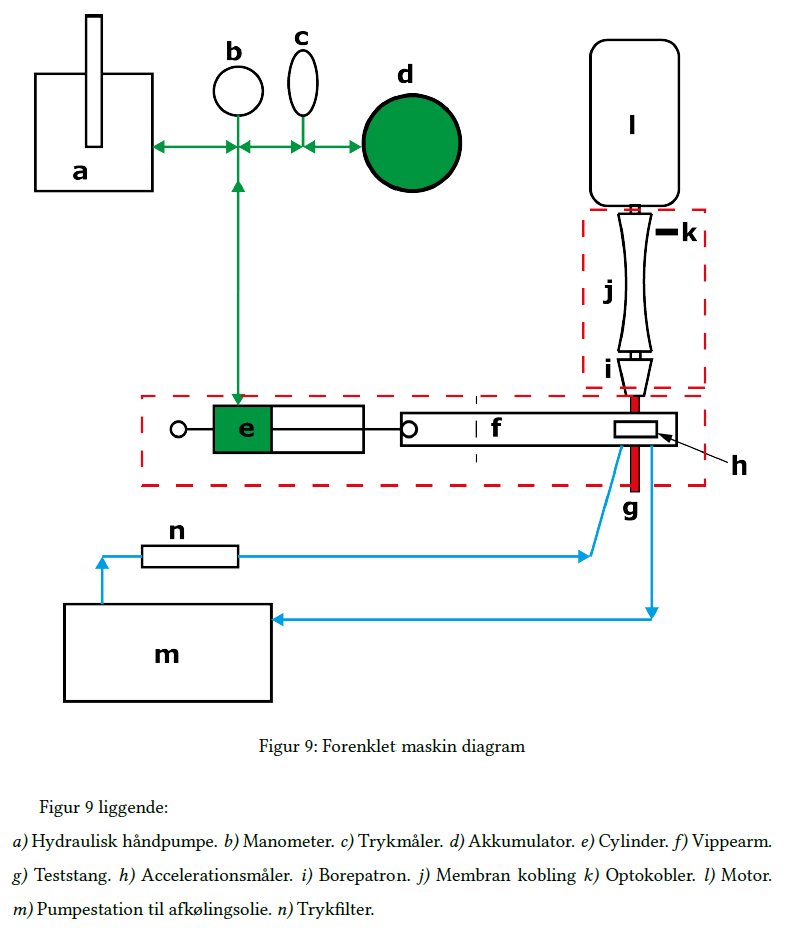
Simplified system diagram of the test rig architecture
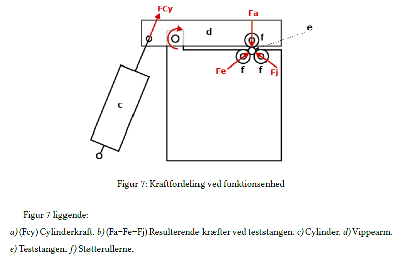
Force distribution in the functional unit.
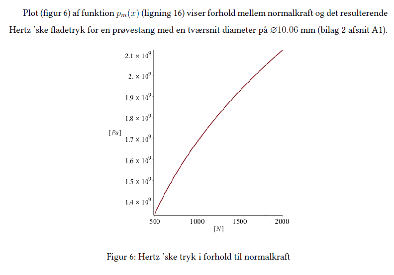
Hertzian pressure as a function of normal force.
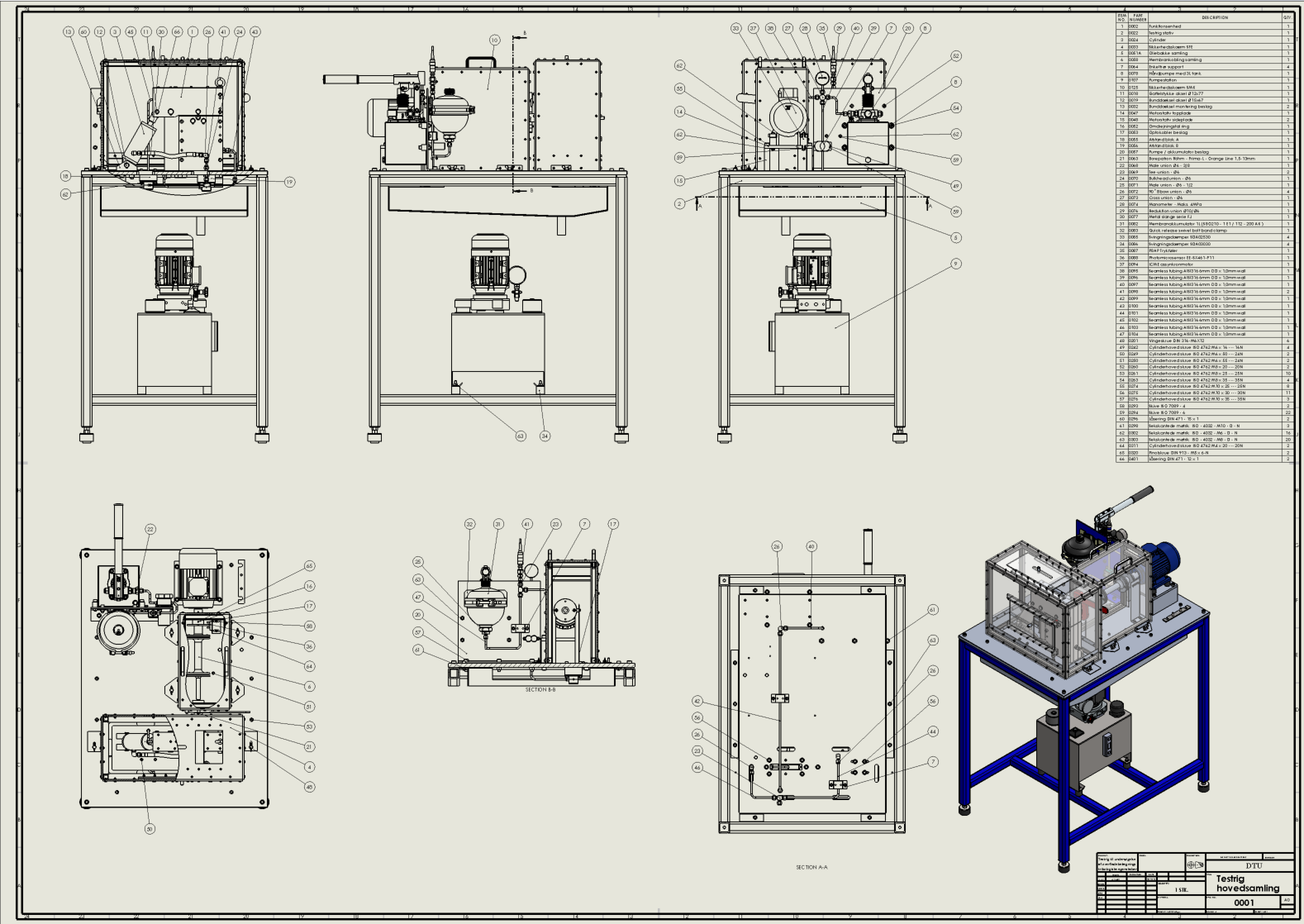
Main assembly drawing of the complete test rig.
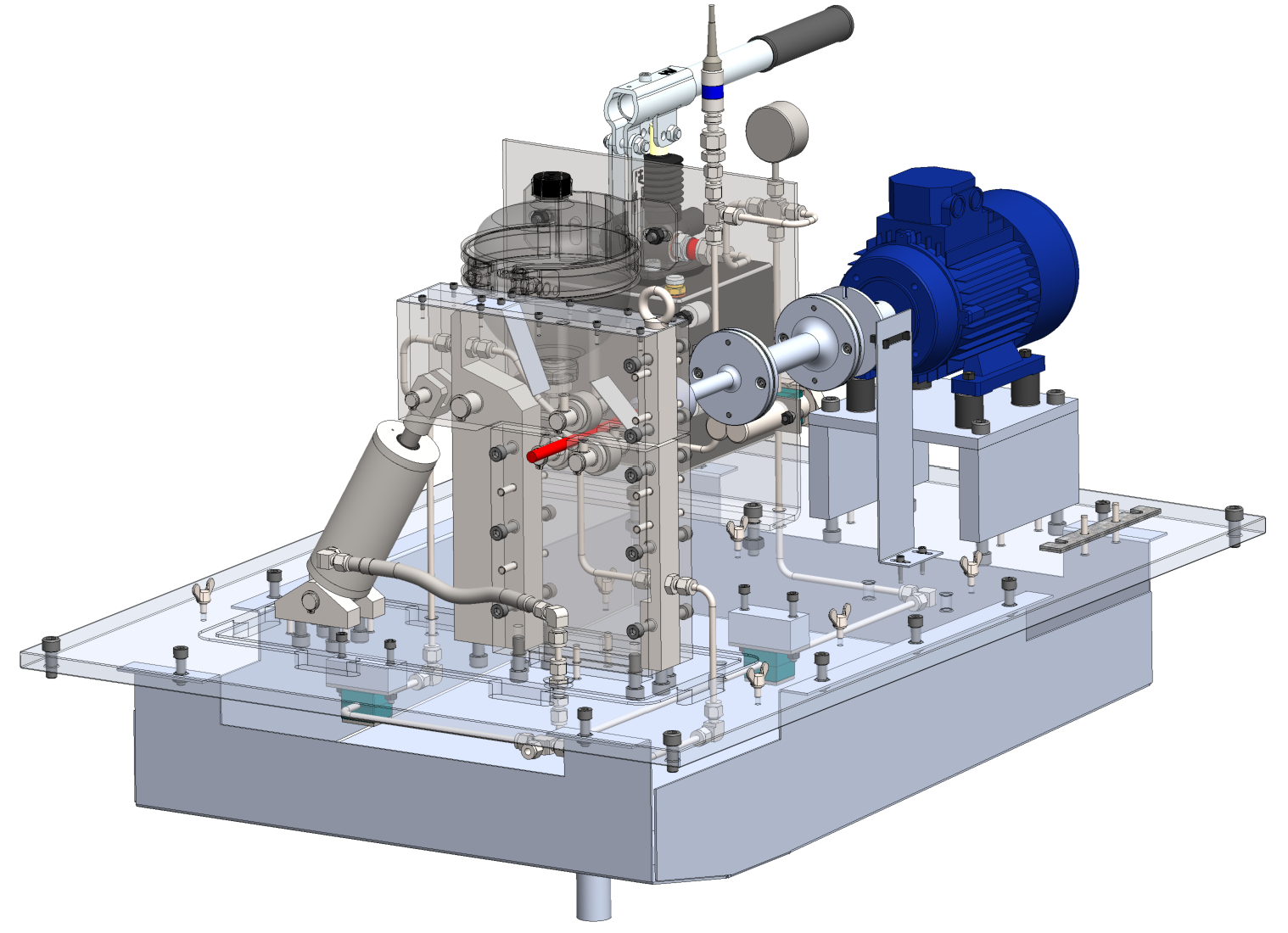
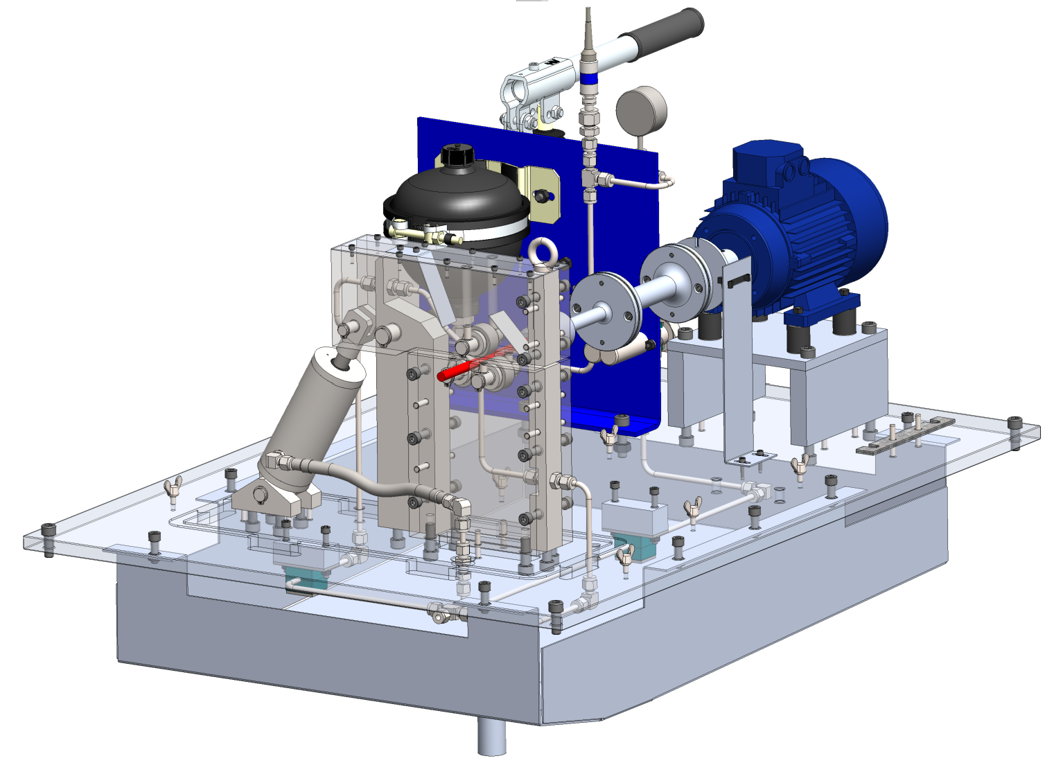
Semi-transparent CAD view showing the internal machine layout.
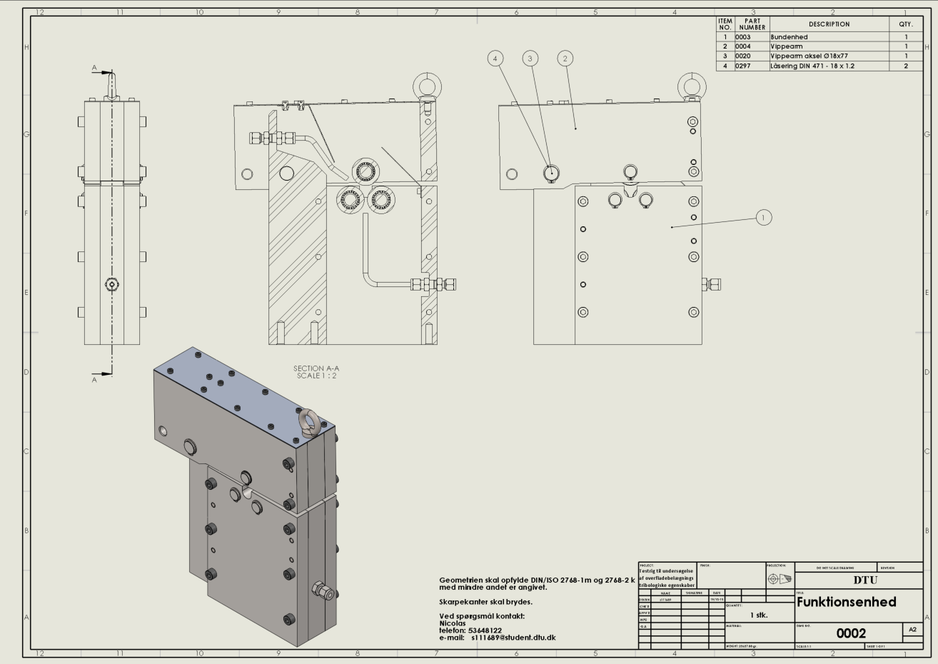
Functional unit assembly at the core of the test principle.
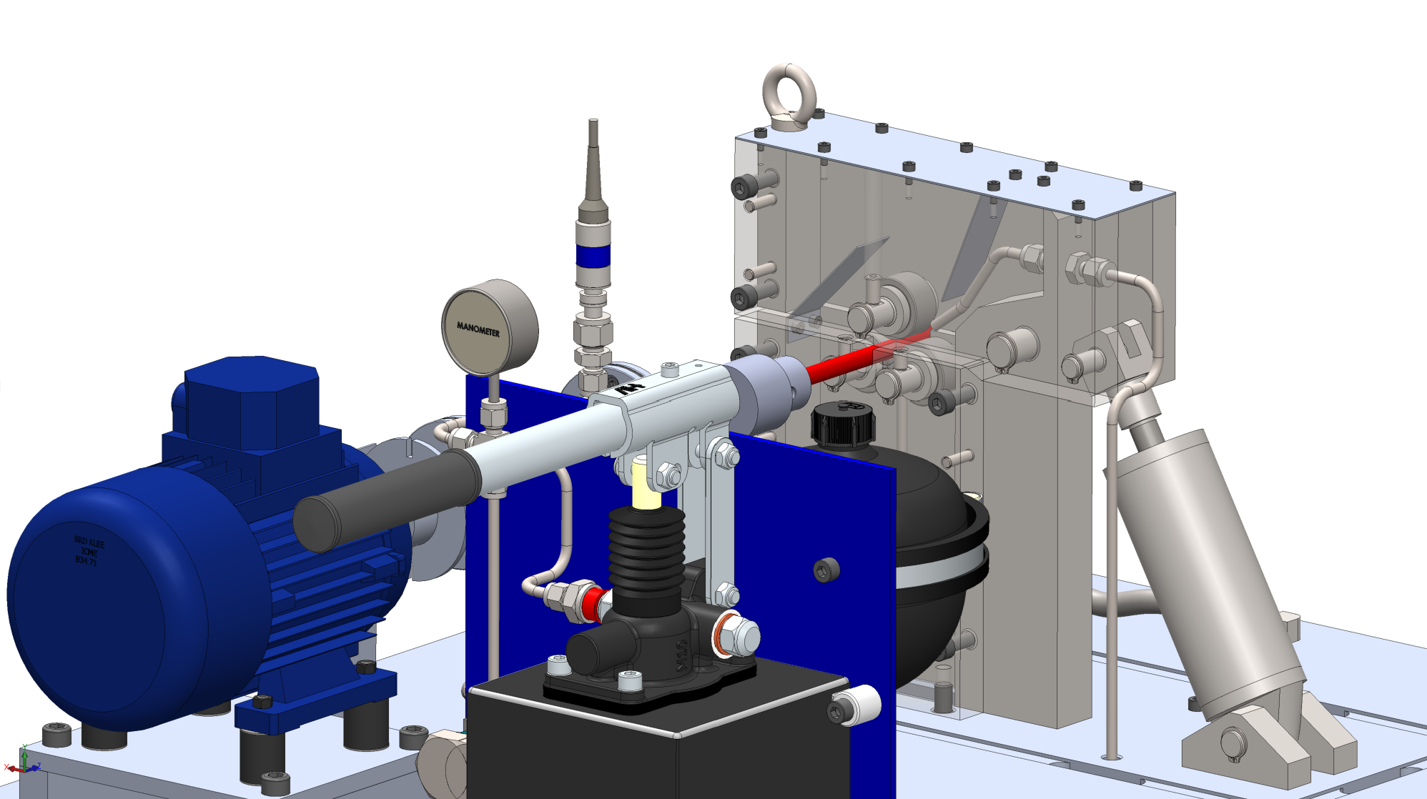
Close-up of the loaded test zone and rod interface.
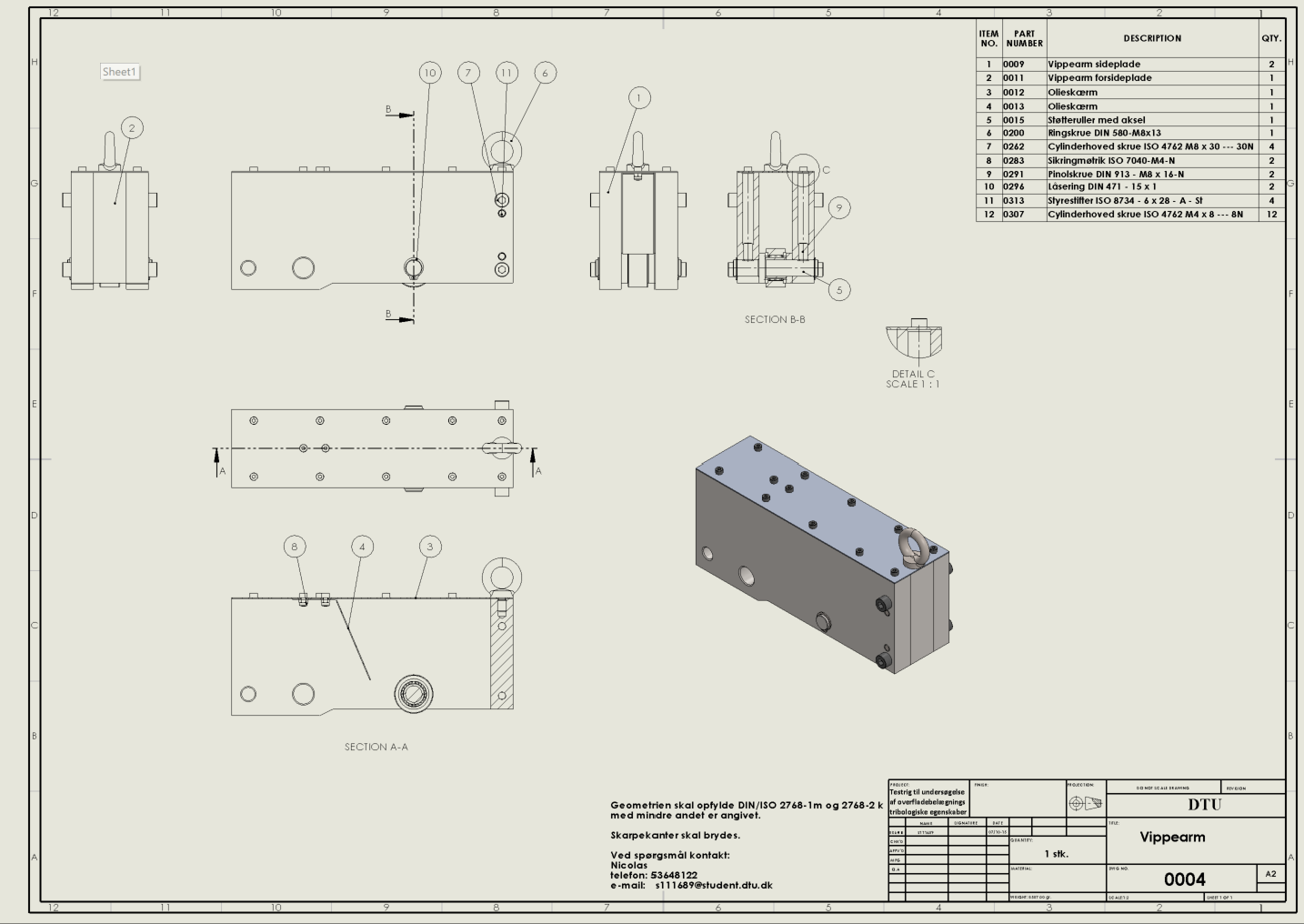
Rocker arm assembly for force transfer to the upper roller.
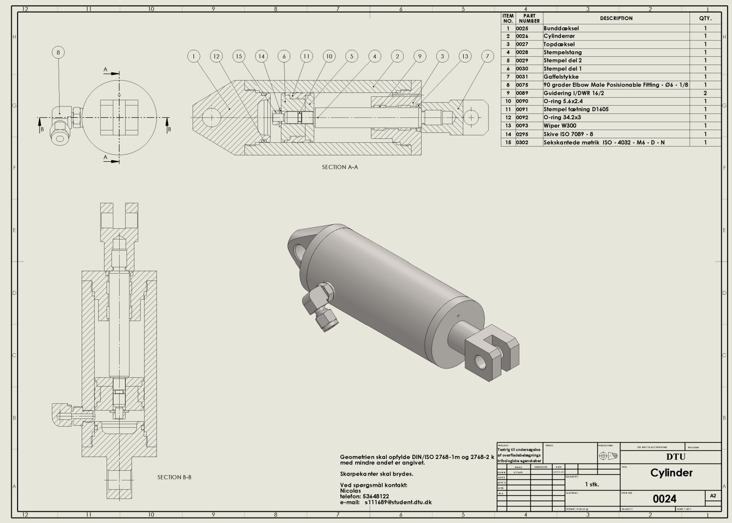
Cylinder assembly for the hydraulic loading mechanism.
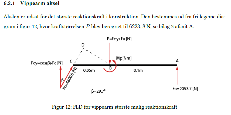
Free-body diagram for verification of the rocker-arm shaft.